Application requirements
I/O density, cycle time, motion or process requirements, field distances and maintenance needs are assessed together. This defines the requirements of the working system, not just individual products.
This machine automation application uses HMI, PLC and servo motion control to address field control, reliable communication and maintainable commissioning.
I/O density, cycle time, motion or process requirements, field distances and maintenance needs are assessed together. This defines the requirements of the working system, not just individual products.
The proposed architecture combines HMI, PLC and servo motion control with the machine’s existing control infrastructure and communication protocols. Final product and module selection depends on site requirements.
ProControl can adapt the solution to local project requirements in Türkiye, from site assessment, I/O planning and protocol selection to panel layout, commissioning and after-sales support.
The technical workflow and visual information from the manufacturer are presented below.
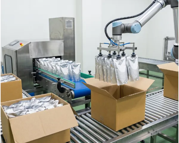
Modern high-speed packaging lines require horizontal flow wrap machines to handle solid material profiles without causing mechanical film deformation or cutting deviation. Traditional machinery built on legacy variable frequency drive (VFD) topologies introduces registration drift and processing lag during material swap-overs. To maintain structural reliability and operational throughput, packaging machinery exporters require standalone hardware architectures that integrate high-speed processing with real-time electronic cam synchronization.
The central FAs PLC acts as the master execution unit, connecting to the HMI display layer as a Modbus slave, while commanding the secondary R8 servo drives via a dedicated RS485 communication network (COM1 master node) configured strictly at 9600 bps, 8N1, with an absolute axis pulse frequency upper limit of 195kHz.
| Input Terminal | Functional Assignment DOCX | Output Terminal | Functional Assignment DOCX |
|---|---|---|---|
| X3 | Cutter Origin Signal (ON Valid) | Y0 | Film-Pulling Pulse Port |
| X4 | Material Photoelectric Eye (ON Valid) | Y1 | Feeding Conveyor Pulse Port |
| X5 | Color-Mark Photoelectric Eye (ON Valid) | Y2 | Rotary Cutter Pulse Port |
| X6 | Physical System Start Button | Y6 | Center-Seal Pneumatic Control |
| X7 | Cycle Pause / Cycle Stop Button | Y7 | Virtual Master Spindle Pulse Port |
| X10 | Emergency Stop Safety Loop | Y10 | Film-Pulling Direction Port |
| X11 | External Jog Button | Y11 | Feeding Conveyor Direction Port |
| X12 | Servo Torque Reached Signal | Y12 | Rotary Cutter Direction Port |
| X13 | Cutter Servo Alarm Line | Y17 | Virtual Master Spindle Direction Port |
| X14 | Film Servo Alarm Line | Y3 (Reserved) | Auxiliary Air Blow Output |
| X15 | Feed Servo Alarm Line | Y4 (Reserved) | Batch Coder Output |
| X16 | Upstream Inline Link Signal | Y5 (Reserved) | Outfeed Material Pusher Cylinder |
| X17 | Downstream Inline Link Signal | — | — |
R8 Servo Parameter Profiles:
The servo drives operate on a single-phase AC 220V power line, supporting external dynamic braking resistors and standard electromagnetic holding brake loops. Key firmware parameters are configured as: P05-00 (Single-Turn Pulse Count, factory set to 10000), P02-00 (D01 Terminal mapped to value 4 for Torque Reached Feedback to X12), and P02-03 (D04 Terminal factory set to 12 for Drive Alarm Outputs to X13~X15).
The touchscreen environment divides machine configuration and diagnostic data into structured setup screens to streamline field commissioning:
To maintain high-speed synchronization without causing film or material deformation, the central PLC control loop executes three segmented electronic cam curves under precise slave-spindle interlocking:
Synchronous Electronic Cam Control Matrix
Driven by a virtual master spindle, the feeding, film-pulling, and rotary cutting axes sync via segmented electronic cam curves. The setup executes automatic velocity scaling, product overlay avoidance, and lag compensation. The short-material cutter speed ratio scales up to 20:1, while long-material runs drop below 1:1, handling large product variance.
Built-in Process & Protection Logic
The software firmware pre-integrates specialized packaging sequences: Product Overlay Dosing Logic (M5300) , Cutter Anti-Jam Automated Reversal (M5302) , Anti-Scorch System Protection (M5301) , and Delayed Center-Seal Cylinder Management (M5303) .
Hardware Trapping & Operational Protection
Features triple physical fault protection arrays— No-Material Alarm (M1030) , Continuous Product Overlay Alarm (M1032) , and Continuous Cutting Fault Alarm (M1031) —combined with real-time servo torque signal monitoring (X12) to block material jamming and prevent tool wear.
The unified Samkoon HMI + PLC + Servo hardware configuration delivers a safe, rugged, and highly adaptive automation standard for horizontal flow wrap lines. By replacing loose, fragmented control links with customizable axis parameters, precise pulse polarity protection, and zero software licensing barriers, Samkoon provides global machinery exporters and packaging system integrators with a clear path toward high-capacity, higher-ROI factory automation.