Multi-Pump Control Panel
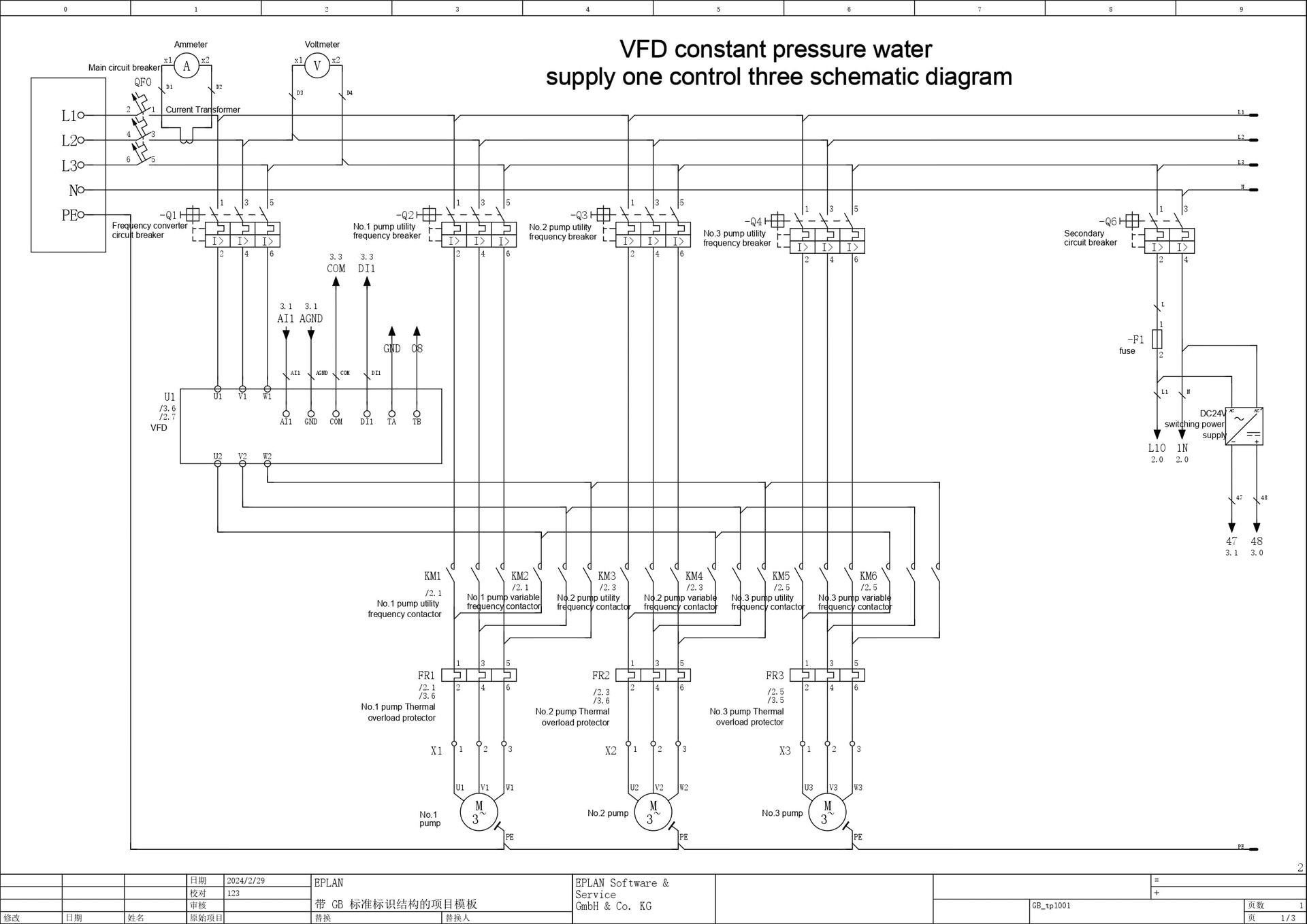
The manufacturer's three-sheet drawing illustrates a constant-pressure system with one drive and three pumps. It is not a fixed-rating cabinet datasheet; the actual panel must be engineered against pump nameplates and site requirements.
Official manufacturer brochure cover — not an exact photo of the configured panel.
Technical specifications
Ratings refer to the linked document revision. Confirm the nameplate, motor current and operating conditions for the exact selection.
Technical specifications
| System architecture | Example schematic: one VFD and three pumps. PDF p. 1 |
|---|
Supply
| Supply drawing | L1/L2/L3/N/PE are shown; no numerical main supply voltage/current rating is stated. PDF p. 1 |
|---|
Protection functions
| Main protection | Main breaker QF0 and a separate drive circuit breaker are shown. PDF p. 1 |
|---|---|
| Pump-circuit protection | Each pump has a separate mains-side breaker and thermal-overload protector in the drawing. PDF p. 1 |
| Water shortage | A separate field connection is shown for water-shortage protection. PDF p. 3 |
Motor and process control
| Mains/drive paths | Two contactors per pump select mains and variable-frequency paths; this is an application schematic. PDF p. 1 |
|---|---|
| Manual control | Manual-mode selection and three individual manual pump-start controls are shown. PDF p. 2 |
| Automatic control | The controller shows an automatic/manual input and pump-control outputs. PDF p. 3 |
Control inputs and outputs
| Pressure feedback | Field terminal blocks for a remote pressure gauge and water sensor are shown; sensor electrical ranges are not specified. PDF p. 3 |
|---|---|
| Control supply | A 24 VDC switching supply is shown; the controller label specifies AC15V or DC24V. PDF p. 1 |
Technical specifications
| Panel indicators | Ammeter, voltmeter, power and pump-running indicators are drawn. PDF p. 1 |
|---|
Operating environment
| Cabinet auxiliaries | Cooling fan, threshold switch and cabinet lighting are shown; these do not establish an IP or temperature rating. PDF p. 2 |
|---|
Document revision and selection notes
Pump powers, panel current, IP class, dimensions, short-circuit rating and component ordering codes are absent
Pump powers, panel current, IP class, dimensions, short-circuit rating and component ordering codes are absent. Do not rewrite the drawing as installation instructions; require an approved project.
PDF p. 1PDF p. 2PDF p. 3
Important note 2
Although the controller has a PUMP4 label, the published system drawing is for three pumps; do not claim four-pump system capacity.
PDF p. 3
Important note 3
These three drawings are example projects; panel power/current capacity, component selection and field wiring must be defined in an approved design matched to pump nameplates and site conditions.
PDF p. 1
Manufacturer drawings
Open connection and dimension drawings in the manufacturer’s original PDF. For installation, use the complete manual matching the exact product model.
PDF p. 1
PDF p. 2
PDF p. 3
Technical documents
See the source links above for document scope and model identity.
Information needed for selection
Providing the following information helps our technical team select the correct product and accessories.
- Panel engineering requires pump count, each pump's power/current, operating/standby sequence, pressure sensor and supply details.
- The drawings are example projects; field installation must follow an approved design by qualified personnel.
Let us verify your application
For Multi-Pump Control Panel selection, share motor, supply, control, environment and duty-cycle data with our engineering team.