VFD510 IP55 AC Drive
VFD510 IP55 is a high-protection drive for environments with dust and water mist. It provides V/F, sensorless vector and encoder-based vector control. Standard Modbus must be distinguished from optional industrial-network cards.
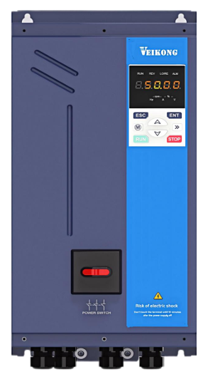
Technical specifications
Ratings refer to the linked document revision. Confirm the nameplate, motor current and operating conditions for the exact selection.
Supply
| Supply | 220 V models: 1/3-phase 200–240 V; 380 V models: 3-phase 380–480 V. PDF p. 10PDF p. 6 |
|---|---|
| Tolerance / frequency | −15…+10% voltage tolerance; 50/60 Hz with ±5% frequency tolerance. PDF p. 10PDF p. 6 |
Output and load capacity
| Output voltage | Three-phase, 0…input voltage. PDF p. 10PDF p. 6 |
|---|---|
| Overload | Heavy duty: 150%/60 s; light duty: 120%/60 s. PDF p. 10PDF p. 6 |
| Frequency | V/F 0–600 Hz; SVC 0–200 Hz; VC 0–400 Hz. PDF p. 10PDF p. 6PDF p. 11 |
Motor and process control
| Control | V/F, sensorless vector (SVC), sensor-based vector (VC). The encoder card must be selected separately. PDF p. 10PDF p. 6 |
|---|---|
| Speed range / accuracy | V/F 1:100 ±0.5%; SVC 1:200 ±0.2%; VC 1:1000 ±0.02%. PDF p. 10PDF p. 6 |
| Carrier frequency | 1–12 kHz, model-dependent. PDF p. 11PDF p. 6 |
| PID / program | Process PID, independent sleep/wake, 16-stage speed and parameter backup/restore. PDF p. 5 |
Communication and options
| Standard / optional communication | Modbus is standard; CANopen, Profinet and Modbus-TCP expansion cards are optional. PDF p. 11PDF p. 6 |
|---|
Control inputs and outputs
| Standard inputs | 5 DI including one pulse input up to 50 kHz; 2 AI, 0–10 V or 0–20 mA. PDF p. 11PDF p. 6 |
|---|---|
| Standard outputs | 1 DO; one high-speed pulse output (0–50 kHz); 2 relays; 2 AO (0–10 V/0–20 mA). PDF p. 11PDF p. 6 |
| I/O expansion | Optional MT500-IOEX1 card: 4 DI, 2 AI, 4 DO; PT100/PT1000/KTY84-130 sensor support. PDF p. 7 |
Protection functions
| STO and protections | STO, ground short-circuit, overcurrent, drive/motor overload and drive-temperature protections are listed. PDF p. 4 |
|---|---|
| IP rating / cooling | Enclosure IP55 with forced-air cooling. The fan's IP65 designation does not make the drive enclosure IP65. PDF p. 4PDF p. 12 |
Selection information
| Braking unit | Built-in braking is described as standard for frames A–C and optional for D and above. Verify the ordering suffix. PDF p. 4 |
|---|---|
| Industries | Illustrated applications include mining, stone processing, metallurgy, manufacturing, wastewater and municipal plants. PDF p. 10 |
Operating environment
| Environmental limits | Normal −10…+40 °C, derated operation up to +50 °C; 1.5% current derating per °C above +40 °C. PDF p. 11PDF p. 6 |
|---|---|
| Altitude/humidity/storage | 0–3000 m; 1%/100 m derating above 1000 m; below 95% RH without condensation; storage −20…+60 °C. PDF p. 12PDF p. 6PDF p. 11 |
Installation and cooling
| Mounting | Wall mounting, away from direct sunlight and electromagnetic-interference sources. PDF p. 6 |
|---|
Commissioning and operation
| Safe installation | The manual requires a qualified electrical professional, de-energised wiring and reliable earthing; it warns to wait 10 minutes after power-off before maintenance. PDF p. 7PDF p. 5 |
|---|---|
| Motor cable / output equipment | For motor cable over 100 m an output AC reactor is recommended; power-factor-correction capacitors must not be added to the drive output. PDF p. 8 |
Model and dimension tables
Check the units and document revision in each table. Wide tables can be scrolled horizontally on small screens.
380 V heavy-duty selection table
| Printed model code | Motor power (kW) | Heavy-duty output current (A) | Frame | Source |
|---|---|---|---|---|
| VFD510-4R0-T4B | 4 | 9.4 | A | PDF p. 6 |
| VFD510-5R5-T4B | 5.5 | 13 | A | PDF p. 6 |
| VFD510-7R5-T4B | 7.5 | 17 | B | PDF p. 6 |
| VFD510-011-T4B | 11 | 25 | B | PDF p. 6 |
| VFD510-015-T4B | 15 | 32 | C | PDF p. 6 |
| VFD510-018-T4B | 18.5 | 37 | C | PDF p. 6 |
| VFD510-022-T4B | 22 | 45 | C | PDF p. 6 |
| VFD510-030-T4(B) | 30 | 60 | D | PDF p. 6 |
| VFD510-037-T4(B) | 37 | 75 | D | PDF p. 6 |
| VFD510-045-T4(B) | 45 | 90 | D | PDF p. 6 |
Additional 2.2 kW rating listed in the manual
| Model | Supply | Rated output current (A) | Frame | Source |
|---|---|---|---|---|
| VFD510-2R2-T4B | 3~380V | 5.6 | A | PDF p. 10 |
Document revision and selection notes
This is the general IP55 drive brochure; it does not establish VFD510-PV MPPT/DC limits.
This is the general IP55 drive brochure; it does not establish VFD510-PV MPPT/DC limits.
PDF p. 6
No 220 V power/current variant table was found in this brochure; do not transfer 380 V currents.
No 220 V power/current variant table was found in this brochure; do not transfer 380 V currents.
PDF p. 6
Manufacturer drawings
Open connection and dimension drawings in the manufacturer’s original PDF. For installation, use the complete manual matching the exact product model.
PDF p. 8
Information needed for selection
Providing the following information helps our technical team select the correct product and accessories.
- Select motor voltage, rated current, heavy/normal duty and the required communication card together.
- Specify installation location, ambient temperature, altitude and motor-cable length. Braking-unit availability depends on frame size.
Let us verify your application
For VFD510 IP55 AC Drive selection, share motor, supply, control, environment and duty-cycle data with our engineering team.