Ripple-Wire Braking Resistor
The RXG20 ripple-resistor family uses a resistance element on a ceramic tube in an open construction. Its datasheet covers 50 W–15 kW rows with individual resistance ranges and mounting dimensions. The open IP00 construction calls for a separate enclosure and thermal-protection assessment.
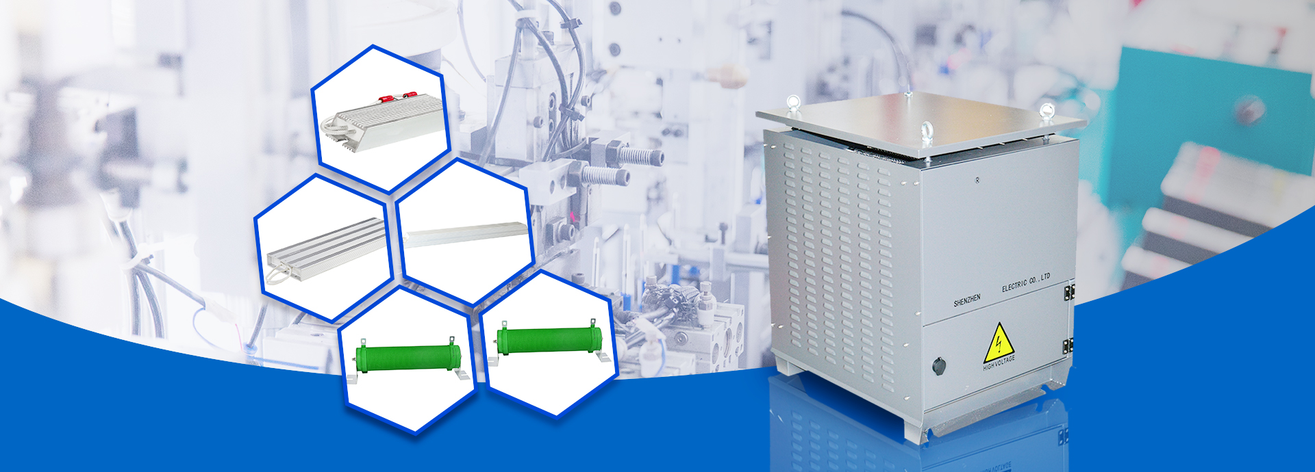
Resistor-family representative image — not an exact photo of the selected resistance and power class.
Technical specifications
Ratings refer to the linked document revision. Confirm the nameplate, motor current and operating conditions for the exact selection.
Technical specifications
| Working voltage | <1.2 kV PDF p. 2 |
|---|---|
| Protection class | IP00 PDF p. 2 |
| Dielectric test | 3 kV AC, 50 Hz, 5 s PDF p. 2 |
| Temperature coefficient | ±400 ppm/°C in the test table PDF p. 2 |
| Tabulated power range | 50–15000 W PDF p. 3 |
Technical specifications
| Construction | Ceramic tube; resistance wire/ribbon; insulating coating; galvanized-steel terminals PDF p. 1 |
|---|
Model and dimension tables
Check the units and document revision in each table. Wide tables can be scrolled horizontally on small screens.
RXG20 power and resistance ranges
These are power-family rows; confirm the exact order code for the required ohmic value with the manufacturer.
| Type | Power (W) | Resistance range (Ω) | Weight (kg) | Figure | Source |
|---|---|---|---|---|---|
| RXG20 | 50 | 1–10000 | 0.2 | A | PDF p. 3 |
| RXG20 | 60 | 1–10000 | 0.2 | A | PDF p. 3 |
| RXG20 | 80 | 1–10000 | 0.2 | A | PDF p. 3 |
| RXG20 | 100 | 1–10000 | 0.2 | A | PDF p. 3 |
| RXG20 | 120 | 1–10000 | 0.2 | A | PDF p. 3 |
| RXG20 | 150 | 1–10000 | 0.4 | A | PDF p. 3 |
| RXG20 | 200 | 1–10000 | 0.4 | A | PDF p. 3 |
| RXG20 | 300 | 1–10000 | 0.55 | B | PDF p. 3 |
| RXG20 | 400 | 1–10000 | 0.65 | B | PDF p. 3 |
| RXG20 | 500 | 1–10000 | 0.85 | B | PDF p. 3 |
| RXG20 | 600 | 1–10000 | 1 | B | PDF p. 3 |
| RXG20 | 800 | 1–10000 | 1.78 | B | PDF p. 3 |
| RXG20 | 1000 | 5–10000 | 1.78 | B | PDF p. 3 |
| RXG20 | 1200 | 5–10000 | 1.96 | B | PDF p. 3 |
| RXG20 | 1500 | 5–10000 | 1.96 | B | PDF p. 3 |
| RXG20 | 1800 | 5–10000 | 1.96 | B | PDF p. 3 |
| RXG20 | 2000 | 5–10000 | 2.35 | B | PDF p. 3 |
| RXG20 | 2500 | 5–10000 | 2.35 | B | PDF p. 3 |
| RXG20 | 3000 | 5–10000 | 2.38 | B | PDF p. 3 |
| RXG20 | 3500 | 5–1000 | 2.8 | B | PDF p. 3 |
| RXG20 | 4000 | 5–1000 | 4.5 | B | PDF p. 3 |
| RXG20 | 5000 | 5–1000 | 4.5 | B | PDF p. 3 |
| RXG20 | 6000 | 5–1000 | 4.5 | B | PDF p. 3 |
| RXG20 | 7000 | 5–1000 | 6.2 | B | PDF p. 3 |
| RXG20 | 8000 | 5–1000 | 6.5 | B | PDF p. 3 |
| RXG20 | 9000 | 5–1000 | 6.5 | B | PDF p. 3 |
| RXG20 | 10000 | 5–1000 | 16 | B | PDF p. 3 |
| RXG20 | 12000 | 5–1000 | 16 | B | PDF p. 3 |
| RXG20 | 15000 | 5–1000 | 16 | B | PDF p. 3 |
RXG20 mounting dimensions (mm)
Letters identify axes in the source drawing; the preserved numbers should not be reinterpreted as a new overall envelope.
| Power (W) | Figure | L1 ±2 | L2 ±5 | L3 ±3 | D ±2 | B | B1 | H | H1 ±3 | N | φd | O | Source |
|---|---|---|---|---|---|---|---|---|---|---|---|---|---|
| 50 | A | 90 | 112 | 134 | 28 | 6.5 | 28 | 28 | 62 | 9.5 | 4.5 | 1.2 | PDF p. 3 |
| 60 | A | 90 | 112 | 134 | 28 | 6.5 | 28 | 28 | 62 | 9.5 | 4.5 | 1.2 | PDF p. 3 |
| 80 | A | 140 | 162 | 184 | 28 | 6.5 | 28 | 28 | 62 | 9.5 | 4.5 | 1.2 | PDF p. 3 |
| 100 | A | 170 | 192 | 214 | 28 | 6.5 | 28 | 28 | 62 | 9.5 | 4.5 | 1.2 | PDF p. 3 |
| 120 | A | 170 | 192 | 214 | 28 | 6.5 | 28 | 28 | 62 | 9.5 | 4.5 | 1.2 | PDF p. 3 |
| 150 | A | 215 | 235 | 241 | 28 | 6.5 | 28 | 28 | 62 | 9.5 | 5.5 | 2 | PDF p. 3 |
| 200 | A | 267 | 287 | 293 | 28 | 6.5 | 28 | 28 | 62 | 9.5 | 5.5 | 2 | PDF p. 3 |
| 300 | B | 260 | 290 | 328 | 40 | 8 | 40 | 45 | 90 | 10 | 4 | 1.2 | PDF p. 3 |
| 400 | B | 300 | 330 | 360 | 40 | 8 | 40 | 45 | 90 | 10 | 4 | 1.2 | PDF p. 3 |
| 500 | B | 300 | 334 | 370 | 50 | 8 | 50 | 45 | 100 | 10 | 4 | 1.2 | PDF p. 3 |
| 600 | B | 330 | 360 | 390 | 50 | 8 | 50 | 45 | 100 | 10 | 4 | 1.2 | PDF p. 3 |
| 800 | B | 300 | 334 | 365 | 60 | 8 | 60 | 55 | 114 | 15 | 6.5 | 2 | PDF p. 3 |
| 1000 | B | 300 | 334 | 365 | 60 | 8 | 60 | 55 | 114 | 15 | 6.5 | 2 | PDF p. 3 |
| 1200 | B | 420 | 445 | 475 | 60 | 8 | 60 | 55 | 114 | 15 | 6.5 | 2 | PDF p. 3 |
| 1500 | B | 420 | 445 | 475 | 60 | 8 | 60 | 55 | 114 | 15 | 6.5 | 2 | PDF p. 3 |
| 1800 | B | 420 | 445 | 475 | 60 | 8 | 60 | 55 | 114 | 15 | 6.5 | 2 | PDF p. 3 |
| 2000 | B | 420 | 455 | 485 | 70 | 8 | 70 | 60 | 125 | 15 | 6.5 | 2 | PDF p. 3 |
| 2500 | B | 420 | 455 | 485 | 70 | 8 | 70 | 60 | 125 | 15 | 6.5 | 2 | PDF p. 3 |
| 3000 | B | 420 | 455 | 485 | 70 | 8 | 70 | 60 | 125 | 15 | 8 | 2 | PDF p. 3 |
| 3500 | B | 510 | 550 | 570 | 70 | 8 | 70 | 60 | 125 | 15 | 8 | 2 | PDF p. 3 |
| 4000 | B | 500 | 535 | 570 | 100 | 8 | 100 | 85 | 180 | 15 | 8 | 2 | PDF p. 3 |
| 5000 | B | 500 | 535 | 570 | 100 | 8 | 100 | 85 | 180 | 15 | 8 | 2 | PDF p. 3 |
| 6000 | B | 500 | 535 | 570 | 100 | 8 | 100 | 85 | 180 | 15 | 8 | 2 | PDF p. 3 |
| 7000 | B | 650 | 685 | 720 | 100 | 8 | 100 | 85 | 180 | 15 | 8 | 2 | PDF p. 3 |
| 8000 | B | 700 | 735 | 770 | 100 | 8 | 100 | 85 | 180 | 15 | 8 | 2 | PDF p. 3 |
| 9000 | B | 700 | 735 | 770 | 100 | 8 | 100 | 85 | 180 | 15 | 8 | 2 | PDF p. 3 |
| 10000 | B | 600 | 655.5 | 696 | 150 | 8 | 150 | 108 | 228 | 18 | 8 | 2 | PDF p. 3 |
| 12000 | B | 600 | 655.5 | 696 | 150 | 8 | 150 | 108 | 228 | 18 | 8 | 2 | PDF p. 3 |
| 15000 | B | 600 | 655.5 | 696 | 150 | 8 | 150 | 108 | 228 | 18 | 8 | 2 | PDF p. 3 |
Document revision and selection notes
Important note 1
The short-overload test uses 10× rated power or the maximum-working-voltage constraint, whichever is more restrictive, for 5 s; resistance change is ≤±(2%R+0.05 Ω). This test is not a repetitive-braking duty rating.
PDF p. 2
Page 2 includes temperature and duty derating curves; the duty graph uses a maximum 120 s cycle
Page 2 includes temperature and duty derating curves; the duty graph uses a maximum 120 s cycle. A graph’s temperature axis must not be presented as the permitted ambient operating range.
PDF p. 2
Manufacturer drawings
Open connection and dimension drawings in the manufacturer’s original PDF. For installation, use the complete manual matching the exact product model.
PDF p. 3
Information needed for selection
Providing the following information helps our technical team select the correct product and accessories.
- What are the drive/chopper minimum resistance, braking energy, pulse duration, repetition interval and ambient temperature?
- How will cabinet cooling, hot-surface protection, fire safety and cable temperature rating be addressed? This datasheet gives no numerical clearance.
Let us verify your application
For Ripple-Wire Braking Resistor selection, share motor, supply, control, environment and duty-cycle data with our engineering team.