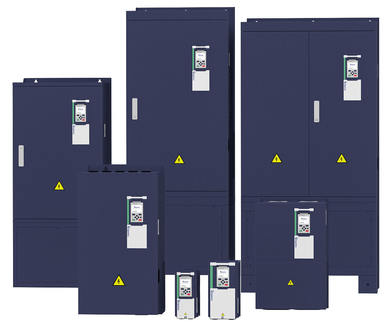
VFD500 General Purpose AC Drive
VFD500 is an industrial drive family for speed and torque control of induction motors. In addition to V/f and sensorless vector, feedback vector operation is available with an appropriate PG card. Heavy- and light-duty current ratings differ; braking and communications options should be verified against the ordered code.
Technical specifications
Ratings refer to the linked document revision. Confirm the nameplate, motor current and operating conditions for the exact selection.
Motor and process control
| Supported motors | Induction-motor control. PDF p. 2 |
|---|---|
| Control modes | V/f, sensorless vector without PG (SVC), feedback vector with PG card (VC). PDF p. 10 |
| Speed and torque | Speed control; torque control in SVC and VC modes. PDF p. 10 |
| Speed range | Speed ranges: V/f 1:100, SVC 1:200, VC 1:1000. PDF p. 10 |
| Speed accuracy | Speed accuracy: V/f ±0.5%, SVC ±0.2%, VC ±0.02%. PDF p. 10 |
| Speed response | Speed response: V/f 5 Hz, SVC 20 Hz, VC 50 Hz. PDF p. 10 |
| Frequency by control mode | V3.19 manual: V/f 0–600 Hz, SVC 0–200 Hz, VC 0–400 Hz. PDF p. 10 |
| Setting resolution | Digital frequency resolution is 0.01 Hz; analogue setting resolution is 0.1% of maximum frequency. PDF p. 10 |
| Ramp settings | Four acceleration/deceleration groups; linear and S-curve, 0–60000 s. PDF p. 11 |
| Application functions | Process PID, sleep/wake, 16-speed operation, virtual I/O and two motor parameter groups are listed. PDF p. 11 |
| Starting / stopping | Direct and flying start; deceleration or coast stop; DC-braking options. PDF p. 11 |
Electrical ratings
| Supply voltage | 220 V class: 200–240 V; 380 V class: three-phase 380–480 V. PDF p. 10 |
|---|---|
| Supply tolerance | Voltage variation −15% / +10%; 50/60 Hz supply with frequency variation <5%. PDF p. 10 |
| Switching frequency | Switching frequency 1–12 kHz depending on model. PDF p. 11 |
Technical specifications
| Overload capacity | General-purpose heavy duty: 150% current for 60 s; light duty: 120% for 60 s. PDF p. 10 |
|---|
Control inputs and outputs
| Digital inputs | Five standard digital inputs; one accepts pulses up to 50 kHz. PDF p. 11 |
|---|---|
| Analogue inputs | Two standard analogue inputs: 0–10 V or 0–20 mA. PDF p. 11 |
| Output configuration | One digital output, one separate 50 kHz pulse output, one standard relay and two analogue outputs; a second relay is optional. PDF p. 11 |
Technical specifications
| I/O expansion | The I/O expansion card adds four DI, two −10…+10 V AI and four DO. PDF p. 11 |
|---|---|
| Feedback options | Incremental-encoder, resolver and frequency-division PG cards are listed; closed loop requires compatible feedback hardware. PDF p. 11 |
Communication and options
| Communications | Modbus is standard; the current catalogue lists CANopen and Profinet as options. PDF p. 11 |
|---|
Installation and cooling
| Operating temperature | Nominal −10…+40 °C; derated operation to +50 °C, reducing rated output current 1.5% per degree above +40 °C. PDF p. 12 |
|---|---|
| Altitude and derating | 0–3000 m; reduce rated output current by 1% per 100 m above 1000 m. PDF p. 11 |
| Environmental conditions | Relative humidity <95%, non-condensing; vibration <5.9 m/s²; storage −20…+60 °C. PDF p. 12 |
| Enclosure protection | IP20, forced-air cooling; clean, ventilated indoor installation. PDF p. 12 |
Selection information
Model and dimension tables
Check the units and document revision in each table. Wide tables can be scrolled horizontally on small screens.
Model and current options
Heavy- and light-duty ratings differ; select by motor nameplate current and duty. Check the catalogue and complete product code for further power options.
| Model code | Supply / voltage class | Motor power | Heavy-duty output current | Light-duty current | Source |
|---|---|---|---|---|---|
| VFD500-R75GT4B | 3 phase, 380–480 V | 0.75 kW | 2.5 A | 4.2 A | PDF p. 8 |
| VFD500-1R5GT4B | 3 phase, 380–480 V | 1.5 kW | 4.2 A | 5.6 A | PDF p. 8 |
| VFD500-2R2GT4B | 3 phase, 380–480 V | 2.2 kW | 5.6 A | 9.4 A | PDF p. 8 |
| VFD500-5R5G/7R5PT4B | 3 phase, 380–480 V | 5.5 kW | 13 A | 17 A | PDF p. 8 |
| VFD500-7R5G/011PT4B | 3 phase, 380–480 V | 7.5 kW | 17 A | 25 A | PDF p. 8 |
| VFD500-011G/015PT4B | 3 phase, 380–480 V | 11 kW | 25 A | 32 A | PDF p. 8 |
| VFD500-015G/018PT4B | 3 phase, 380–480 V | 15 kW | 32 A | 37 A | PDF p. 8 |
| VFD500-018G/022PT4B | 3 phase, 380–480 V | 18.5 kW | 37 A | 45 A | PDF p. 8 |
| VFD500-022G/030PT4B | 3 phase, 380–480 V | 22 kW | 45 A | 60 A | PDF p. 8 |
| VFD500-030G/037PT4 | 3 phase, 380–480 V | 30 kW | 60 A | 75 A | PDF p. 8 |
| VFD500-037G/045PT4 | 3 phase, 380–480 V | 37 kW | 75 A | 90 A | PDF p. 8 |
| VFD500-045G/055PT4 | 3 phase, 380–480 V | 45 kW | 90 A | 110 A | PDF p. 8 |
| VFD500-055G/075PT4 | 3 phase, 380–480 V | 55 kW | 110 A | 152 A | PDF p. 8 |
| VFD500-075G/090PT4 | 3 phase, 380–480 V | 75 kW | 152 A | 176 A | PDF p. 8 |
| VFD500-090G/110PT4 | 3 phase, 380–480 V | 90 kW | 176 A | 210 A | PDF p. 8 |
Enclosure and mounting dimensions
Compare the full product code and enclosure drawing before installation. Dimensions can differ between hardware revisions.
| Scope | Width | Height | Depth | Mounting pitches | Hole diameter | Source |
|---|---|---|---|---|---|---|
| 0.75–4 kW | 100 mm | 215 mm | 170 mm | 87 × 206.5 mm | 5 mm | PDF p. 20 |
| 5.5–7.5 kW | 130 mm | 250 mm | 180 mm | 113 × 239.5 mm | 5 mm | PDF p. 20 |
| 11–15 kW | 170 mm | 310 mm | 193 mm | 153 × 299 mm | 6 mm | PDF p. 20 |
| 18.5–22 kW | 210 mm | 370 mm | 196 mm | 165 × 350 mm | 6 mm | PDF p. 20 |
| 30–37 kW | 260 mm | 452.5 mm | 230 mm | 218 × 438 mm | 7 mm | PDF p. 20 |
Document revision and selection notes
The manual used is V3.19 / July 2025
The manual used is V3.19 / July 2025. Select network and braking hardware by the full order code. A reference to STO alone does not verify a specific SIL/PL certification.
PDF p. 11
The 4R0 model code has a 3.7 kW motor-power cell in the manual
The 4R0 model code has a 3.7 kW motor-power cell in the manual. Do not silently normalise it to 4.0 kW without checking the nameplate.
PDF p. 8
VC starting torque is 200% in the manual but 180% in the brochure specification table; avoid an unconditional claim.
VC starting torque is 200% in the manual but 180% in the brochure specification table; avoid an unconditional claim.
PDF p. 10PDF p. 11
Important note 4
The V3.19 table does not clearly separate TCP/CANopen/Profinet under its Standard heading; the brochure calls CANopen/Profinet optional.
PDF p. 11PDF p. 11
Important note 5
Conflicting/revision-specific document information; confirm the ordered unit: Manual: V/f 150% at 0.5 Hz, SVC 180% at 0.25 Hz, VC 200% at 0 Hz.
PDF p. 10
Manufacturer drawings
Open connection and dimension drawings in the manufacturer’s original PDF. For installation, use the complete manual matching the exact product model.
PDF p. 20
Information needed for selection
Providing the following information helps our technical team select the correct product and accessories.
- What does the complete motor nameplate state: phase, voltage, rated current, power and motor type?
- What starting torque, braking requirement and duty cycle does the load require?
- Will control use terminals, an analogue signal, communications or encoder feedback?
- What are the cabinet temperature, altitude, motor-cable length and available mounting space?
Let us verify your application
For VFD500 General Purpose AC Drive selection, share motor, supply, control, environment and duty-cycle data with our engineering team.