VFD580 High-End AC Drive
VFD580 combines speed, torque and position control in a high-performance AC drive family. Control and encoder options support induction and synchronous-motor applications. Selection must consider the exact model, motor current, feedback board, braking hardware and enclosure conditions together. Features specific to VFD586 must not be advertised as standard VFD580 equipment.
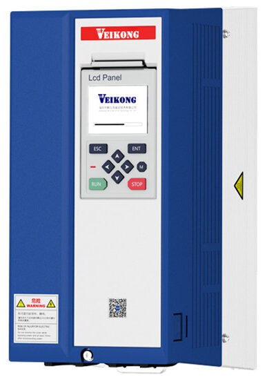
Technical specifications
Ratings refer to the linked document revision. Confirm the nameplate, motor current and operating conditions for the exact selection.
Electrical ratings
| Main supply | The 220 V class accepts single/three-phase 200–240 V; the 400 V class accepts three-phase 380–480 V. PDF p. 14 |
|---|---|
| Supply tolerance | Input-voltage variation −15% / +10%; 50/60 Hz supply with frequency variation below 5%. PDF p. 14 |
| Output voltage | Three-phase output voltage ranges from zero to the input voltage. PDF p. 14 |
| DC reactor | A built-in DC reactor is specified for frame C and larger. PDF p. 14 |
| Switching frequency | Carrier frequency is 1–16 kHz depending on model. PDF p. 14 |
Technical specifications
| Overload capacity | 150% rated current for 60 s, 180% for 10 s and 200% for 2 s. PDF p. 14 |
|---|
Motor and process control
| Control modes | V/f, sensorless vector (SVC) and feedback vector (VC); speed, torque in SVC/VC, and servo position control. PDF p. 14 |
|---|---|
| Speed range | Speed range: V/f 1:100, SVC 1:200, VC 1:1000. PDF p. 14 |
| Standard frequency range | Standard output frequency is 0–600 Hz; verify any high-frequency version separately. PDF p. 14 |
| Starting torque | Starting torque: V/f 150% at 0.5 Hz; SVC 180% at 0.25 Hz; VC 180% at 0 Hz. PDF p. 14 |
| Torque accuracy | Torque accuracy is stated as 8% in SVC up to 5 Hz, 5% above 5 Hz, and 3% in VC. PDF p. 14 |
| Ramp settings | Four acceleration/deceleration groups with linear and S-curve options. PDF p. 14 |
| Starting / stopping | Direct start or speed-search start for a spinning motor; deceleration, DC-braked or coast stop. PDF p. 14 |
Technical specifications
| Standard encoder input | The standard incremental-encoder input accepts differential signals up to 500 kHz or open-collector signals up to 100 kHz. PDF p. 15 |
|---|---|
| Motor temperature sensor | PT100, PT1000 and KTY84-130 sensors are listed for the standard motor-temperature input. PDF p. 15 |
Technical specifications
| Feedback options | Slot 1 accepts incremental, resolver, sine/cosine and Tamagawa absolute-encoder boards. PDF p. 12PDF p. 15 |
|---|
Communication and options
| Communication boards | Modbus RTU, CANopen and Profinet options are listed through slot 2; EtherCAT is specific to VFD586. PDF p. 12PDF p. 15 |
|---|
Control inputs and outputs
| Digital inputs | Seven digital inputs; HDI is one of them and accepts pulses up to 50 kHz. PDF p. 15PDF p. 40 |
|---|---|
| Analogue inputs | Wiring diagram: AI1 −10…+10 V; AI2 and AI3 selectable for 0–10 V or 0–20 mA. PDF p. 40 |
| Digital outputs | The diagram shows two digital outputs in total, DO1 and HDO; HDO can act as a high-speed pulse output. PDF p. 40 |
| Relay outputs | Two relay outputs through T1A/T1B/T1C and T2A/T2B/T2C. PDF p. 40 |
| Analogue outputs | AO1: 0–10 V; AO2: selectable 0–10 V or 0–20 mA. PDF p. 40 |
Operation
| Keypad options | Panel configurations include MTBOP1 LED, MTBOP2 rotary-control LED and MTSOP1 LCD. PDF p. 12PDF p. 15 |
|---|
Installation and cooling
| Enclosure protection | IP21 with forced-air cooling; through-panel installation requires separate accessories. PDF p. 15 |
|---|---|
| Altitude and derating | Installation range 0–3000 m; derate 1% per 100 m above 1000 m. PDF p. 15 |
| Humidity and storage | Relative humidity below 95%, non-condensing; storage −20…60 °C. PDF p. 15 |
Selection information
| Long motor cables | An output AC reactor is recommended for motor cables over 100 m; do not connect power-factor capacitors to the output. PDF p. 11 |
|---|
Protection functions
| Protection functions | Protection covers output-to-earth short circuit, overcurrent, drive/motor overload and drive temperature, with motor-temperature protection using a sensor. PDF p. 6 |
|---|
Model and dimension tables
Check the units and document revision in each table. Wide tables can be scrolled horizontally on small screens.
Model and current options
S2B denotes the single-phase and T2B the three-phase 220 V variant. A bracketed B denotes the braking-unit option; verify the full order code and motor current.
| Model code | Supply / voltage class | Motor power | Rated output current | Source |
|---|---|---|---|---|
| VFD580-2R2-T4B | 3 phase, 400 V | 2.2 kW | 5.6 A | PDF p. 13 |
| VFD580-4R0-T4B | 3 phase, 400 V | 4 kW | 9.4 A | PDF p. 13 |
| VFD580-5R5-T4B | 3 phase, 400 V | 5.5 kW | 13 A | PDF p. 13 |
| VFD580-7R5-T4B | 3 phase, 400 V | 7.5 kW | 17 A | PDF p. 13 |
| VFD580-011-T4B | 3 phase, 400 V | 11 kW | 25 A | PDF p. 13 |
| VFD580-015-T4B | 3 phase, 400 V | 15 kW | 32 A | PDF p. 13 |
| VFD580-018-T4B | 3 phase, 400 V | 18.5 kW | 37 A | PDF p. 13 |
| VFD580-022-T4B | 3 phase, 400 V | 22 kW | 45 A | PDF p. 13 |
| VFD580-030-T4B | 3 phase, 400 V | 30 kW | 60 A | PDF p. 13 |
| VFD580-037-T4B | 3 phase, 400 V | 37 kW | 75 A | PDF p. 13 |
| VFD580-045-T4(B) | 3 phase, 400 V | 45 kW | 90 A | PDF p. 13 |
| VFD580-055-T4(B) | 3 phase, 400 V | 55 kW | 110 A | PDF p. 13 |
| VFD580-075-T4(B) | 3 phase, 400 V | 75 kW | 152 A | PDF p. 13 |
| VFD580-090-T4(B) | 3 phase, 400 V | 90 kW | 176 A | PDF p. 13 |
| VFD580-110-T4 | 3 phase, 400 V | 110 kW | 210 A | PDF p. 13 |
| VFD580-132-T4 | 3 phase, 400 V | 132 kW | 253 A | PDF p. 13 |
| VFD580-160-T4 | 3 phase, 400 V | 160 kW | 304 A | PDF p. 13 |
| VFD580-185-T4 | 3 phase, 400 V | 185 kW | 360 A | PDF p. 13 |
| VFD580-200-T4 | 3 phase, 400 V | 200 kW | 380 A | PDF p. 13 |
| VFD580-220-T4 | 3 phase, 400 V | 220 kW | 426 A | PDF p. 13 |
| VFD580-250-T4 | 3 phase, 400 V | 250 kW | 465 A | PDF p. 13 |
| VFD580-280-T4 | 3 phase, 400 V | 280 kW | 520 A | PDF p. 13 |
| VFD580-315-T4 | 3 phase, 400 V | 315 kW | 585 A | PDF p. 13 |
| VFD580-355-T4 | 3 phase, 400 V | 355 kW | 650 A | PDF p. 13 |
| VFD580-0R7-S2B (T2B) | S2B: single phase / T2B: three phase, 220 V | 0.75 kW | 5.6 A | PDF p. 13 |
| VFD580-1R5-S2B (T2B) | S2B: single phase / T2B: three phase, 220 V | 1.5 kW | 8 A | PDF p. 13 |
| VFD580-2R2-S2B (T2B) | S2B: single phase / T2B: three phase, 220 V | 2.2 kW | 10.6 A | PDF p. 13 |
| VFD580-4R0-S2B (T2B) | S2B: single phase / T2B: three phase, 220 V | 4 kW | 17 A | PDF p. 13 |
| VFD580-5R5-S2B (T2B) | S2B: single phase / T2B: three phase, 220 V | 5.5 kW | 25 A | PDF p. 13 |
| VFD580-7R5-S2B (T2B) | S2B: single phase / T2B: three phase, 220 V | 7.5 kW | 32 A | PDF p. 13 |
| VFD580-011-S2B (T2B) | S2B: single phase / T2B: three phase, 220 V | 11 kW | 45 A | PDF p. 13 |
| VFD580-015-S2B (T2B) | S2B: single phase / T2B: three phase, 220 V | 15 kW | 60 A | PDF p. 13 |
| VFD580-018-S2B (T2B) | S2B: single phase / T2B: three phase, 220 V | 18.5 kW | 75 A | PDF p. 13 |
Enclosure and mounting dimensions
Compare the full product code and enclosure drawing before installation. Dimensions can differ between hardware revisions.
Document revision and selection notes
This page concerns VFD580
This page concerns VFD580. VFD586 EtherCAT and SSI/BISS features in the shared catalogue have not been carried over.
PDF p. 6
The manual requires 1.5%/°C derating above 40 °C; the brochure claims no derating at 50 °C
The manual requires 1.5%/°C derating above 40 °C; the brochure claims no derating at 50 °C. Do not state 50 °C nominal without confirming the supplied hardware.
PDF p. 15PDF p. 3PDF p. 6
Standard 600 Hz agrees; high frequency is 2000 Hz in the manual but VFD580 1200 Hz / VFD586 2500 Hz in the brochure
Standard 600 Hz agrees; high frequency is 2000 Hz in the manual but VFD580 1200 Hz / VFD586 2500 Hz in the brochure. Confirm the special version.
PDF p. 14PDF p. 4PDF p. 7
The manual gives SVC ±0.2% / VC ±0.01%; brochure performance text gives SVC ±0.5% / VC ±0.02%
The manual gives SVC ±0.2% / VC ±0.01%; brochure performance text gives SVC ±0.5% / VC ±0.02%. Conditions/version are unresolved.
PDF p. 14PDF p. 4
Important note 5
The manual summary says AI1 0–10 V and is ambiguous about digital output count; the detailed diagram shows AI1 −10…+10 V and two outputs, DO1/HDO. The brochure I/O table supports the detailed diagram.
PDF p. 15PDF p. 40PDF p. 8
The slot-2 extension has one additional digital input in the manual and two in the brochure
The slot-2 extension has one additional digital input in the manual and two in the brochure. Confirm the fitted board code.
PDF p. 15PDF p. 8
For example, 160 kW is frame G in the manual but H in the brochure
For example, 160 kW is frame G in the manual but H in the brochure. Confirm large-frame dimensions against the actual order code.
PDF p. 13PDF p. 7
The ramp limit is 60000 s in the manual versus 6000 s in the brochure
The ramp limit is 60000 s in the manual versus 6000 s in the brochure. Publish only the verified four groups and curve types.
PDF p. 14PDF p. 7
Important note 9
Conflicting/revision-specific document information; confirm the ordered unit: The manual table states speed accuracy of V/f ±0.5%, SVC ±0.2%, VC ±0.01%.
PDF p. 14
Important note 10
Conflicting/revision-specific document information; confirm the ordered unit: The manual specifies −10…40 °C nominal, up to 50 °C, with 1.5% derating per °C above 40 °C.
PDF p. 15
Manufacturer drawings
Open connection and dimension drawings in the manufacturer’s original PDF. For installation, use the complete manual matching the exact product model.
PDF p. 40
PDF p. 22
Information needed for selection
Providing the following information helps our technical team select the correct product and accessories.
- What does the complete motor nameplate state: phase, voltage, rated current, power and motor type?
- What starting torque, braking requirement and duty cycle does the load require?
- Will control use terminals, an analogue signal, communications or encoder feedback?
- What are the cabinet temperature, altitude, motor-cable length and available mounting space?
Let us verify your application
For VFD580 High-End AC Drive selection, share motor, supply, control, environment and duty-cycle data with our engineering team.