Supports two-channel SSI encoder input
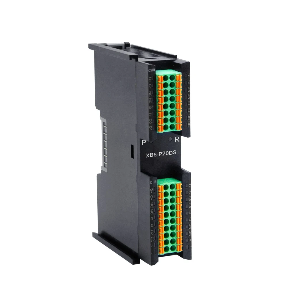
Solidot · Pulse Counter Module
XB6-P20DS
SSI absolute encoder counting module, supports two channels of 10-40 bit SSI encoder signal input. The SSI encoder clock frequency can reach 2.0MHz and supports Gray code and binary code. It also supports setting the data bit length and position, setting endianness for upstream data, bidirectional counting, and pulse capture function.
Pulse Counter Module
Backplane ProtocolX-bus
Number of Inputs4
Input Current4 mA
What defines this model
Review the published differences attached to this exact model code rather than only the general family.
Frame length, LSB and MSB can be set
Supports bidirectional counting, encoder rotation in both directions, flexible adaptation to the direction of counting
Can capture count value when trigger channel is in capture mode
Place in the system architecture
Treat network, product and field layers as one validation flow.
Network and host-controller compatibility
Channel, interface and function selection
Power, connection, environment and mechanical layout
Technical parameters
Values come from Solidot's current official model record and must be reconfirmed for the product revision.
Interface Parameters
| Backplane Protocol | X-bus |
|---|---|
| Connection Method | Push in spring connection |
| Data Transfer Medium | X-bus backplane bus |
| Data Transfer Rates | 6Mb/s |
| Electrical Isolation | Yes |
Technical Parameters
| Current Consumption | 45mA |
|---|---|
| Rated voltage | 5VDC |
| Operating Temperature | -10~60℃ |
| Relative Humidity | 95%, no coagulation |
| Storage Temperature | -20~75℃ |
| Protect. Class | IP20 |
| Module Size | 106*73*25.7mm (installation width 22.5mm) |
| Weight | 100g |
Digital Input
| Nominal Voltage | 24 VDC(±25%) |
|---|---|
| Number of Inputs | 4 |
| Transistor Polarity | NPN/PNP |
| Input Current | 4 mA |
| Electrical Isolation | 500 V |
| Indicator | Green LED |
| “1” Signal Voltage | 15~30 V (PNP) -3~+3 V (NPN) |
| Isolation Method | Optocoupler isolation |
Digital Output
| Nominal Voltage | 24 VDC(±25%) |
|---|---|
| Number of Outputs | 4 |
| Transistor Polarity | PNP |
| Load Type | Resistive load, inductive load |
| Max. Output Current | Max:500 mA |
| Port Protection | Overcurrent protection |
| Electrical Isolation | 500 V |
| Indicator | Green LED |
| Isolation Method | Optocoupler isolation |
Functional Parameters
| Process data volume: Downlink | 2 Byte |
|---|---|
| Process data volume: Upstream | 20 Byte |
| Digital IO | Input: 4 Ch,PNP/NPNOutput: 4 Ch,PNP |
| Encoder Input | 2 channels |
| Refresh rate | 1 ms |
| Encoder signal type | Differential signal,5V |
| Data frame length | 10~40 bits |
| Position Value Format | Supports Gray code or binary |
| LSB/MSB Position Value | Can be set |
| SSI encoder clock frequency | ≤2.0 MHz |
| Read Interval Time | Can be set |
| Capture Function | Support |
Product images
Images are official source records for the same model.
Official files
Only links published by the manufacturer for this model are listed.
Frequently asked questions
Core checks before selection and commissioning.
Which industrial network does XB6-P20DS support?
Network support must be confirmed from the exact model code and current official documentation.
What are the principal published specifications?
Backplane Protocol: X-bus; Number of Inputs: 4; Input Current: 4 mA; Encoder Input: 2 channels
How should this model be selected?
Evaluate network, channel function, power, environment, wiring and mechanical placement as one configuration. ProControl can verify the final bill of materials.
Other models in this category
Compare protocol, channel architecture and environmental limits.
Manufacturer source
Technical data and images are based on the current official Solidot product record. Verify revision-sensitive values before ordering or commissioning. Open official record
Validate the right Solidot XB6-P20DS architecture with ProControl
Share the network, signal count, environment and installation constraints; our engineering team will review the complete configuration.